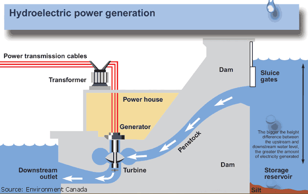
Penstocks are pipes connecting the end of the headrace channel/tunnel to the turbines or pumps of a hydropower plant. They experience pressure close to the drop height. They are made of steel pipes, reinforced concrete, and sometimes of plastic or composites. The connection between intake structures and penstocks/pressure tunnels is either made with a surge chimney or by a surge chamber if the intake channel is free flow, to help reduce overpressure due to water hammer in the penstock and in the headrace tunnel, caused by sudden load (flow) changes.
The surge chimney is generally a vertical cylindrical tank excavated into the rock. At the downstream toe of the penstock, just upstream of the powerhouse, the manifold is the pipe that divides the flow into as many penstocks as turbines. Every penstock arriving at the powerhouse is equipped with a butterfly valve or a spherical valve to shut off the flow.

Penstock is a conduit or tunnel connecting a reservoir/forebay to a hydro turbine housed in a powerhouse building for power generation. It withstands the hydraulic pressure of water under static as well as dynamic conditions. It contains the closing devices (gates/valves) at the starting (just after the reservoir/forebay) and at the tail end just before the turbine to control the flow in the penstock.
The penstock material may be mild steel, glass reinforced plastic (GRP), reinforced cement concrete (RCC), wood stave, cast iron, and high-density polyethylene (HDPE), etc. However, in most cases, mild steel has been used for penstock for a long due to wider applicability and availability. The penstock cost contributes an appreciable percentage towards the total civil works cost of the hydroelectric project. By optimizing the penstock diameter, maximum energy generation can be obtained at a minimum cost.

Hydromechanical equipment manufacturers are under strong and growing pressure to innovate. In Europe, the decarbonization agenda is requiring the improvement of hydro equipment, while abroad other manufacturers are threatening to take market share from a sector that is a valuable source of export earnings for the European economy. The market for large hydropower plants is dominated by a few manufacturers of large equipment and several suppliers of auxiliary components and systems.
Over the past decades, no breakthroughs but continuous developments have occurred with the basic machinery; computer technology and digitalization have led to significant improvements in many areas, such as monitoring, diagnostics, protection, and control. Operators, manufacturers, and suppliers need to invest significant resources into research and development to meet advances in operation and technology and to deal with market competition for hydromechanical equipment.
Large hydropower plants may have a considerable impact on environmental and socioeconomic aspects at the regional level. Therefore, the link between industry, R&D, and policy institutions is important to the development of this energy sector. Unlike large plants, small-scale hydropower installations comprise a huge variety of designs, layouts, equipment, and materials for hydromechanical installation especially penstock, the pressure conduit that governs the flow of water for scale projects. Therefore, state-of-the-art technologies, knowledge, and design experience are key to fully exploiting local resources at competitive costs and without significant adverse environmental impact.
Upgrading offers a way to maximize the energy produced from existing hydropower plants and may offer a less expensive opportunity to increase hydropower production. Penstocks supply one or more hydraulic units with high-pressure water. Penstock engineering and construction involve different disciplines like civil engineering and pressure vessel making.
In addition, Penstocks are usually made of steel and they must be able to withstand high pressures on the inside surface in the event of a sudden increase or decrease in the load - the so-called water hammer. If the powerhouse is located far from the dam and reservoir, water is transferred by open channels, tunnels under pressure, or pressure shafts, which depending upon the rock type can be unlined, or lined with concrete or steel. A sufficient water head should be available above the intake entrance to avoid the formation of vortices which may carry air into the penstock and result in problems with turbine operation.

In a broader context, Penstock, a closed conduit, is an important component of hydropower projects. Various methods are available for the optimum design of penstock. Those methods are either based on empirical relations or derived analytically by optimizing the friction loss in the penstock. Penstock designs have been compared to review their suitability.
A new method has been developed for the optimum design of penstock based on minimizing the total head loss comprising friction and other losses. By using the newly developed method, the diameter and the annual cost of penstocks for a few Hydro Electric plants of varying capacities have been worked out and a reduction in the annual cost of penstocks has been found in comparison to the penstock cost for those projects. The optimum diameter of penstock is computed based on minimizing the total annualized cost of the penstock comprising of annualized expenditure on penstock and an annual loss of revenue for energy loss caused by head losses in the pipe. For smaller diameter penstock, the expenditure on penstock will be less but, this will have a higher head loss leading to higher energy and revenue loss. Similarly, the larger diameter penstock will have less head loss resulting in more energy generation and higher revenue but, will have more installation cost leading to a higher annual cost of penstock. Therefore, head loss in penstock affects the determination of the optimum diameter of the penstock.
The head loss in penstock comprises friction loss (hf) due to resistance offered by the penstock's inner surface and other losses. The sources of other head losses (h0) are specials comprising of intake provided at the entry of penstock with reservoir to allow smooth entry of discharge into the penstock, control equipment (gate or valve) provided with penstock outside the reservoir/forebay to control the penstock discharge, bends provided at each location of the change in penstock alignment, bifurcation (wye) piece provided at the end of penstock to connect it with its branches (one each for each unit), inlet valve provided at the end of each penstock branch to control the flow entering the turbine and transition piece (expansion or reducer) provided before or after inlet valve to connect it with penstock branch or with the turbine. The head loss also occurs at the trash rack provided in front of the penstock intake which checks the entry of floating and other materials into the penstock. The head loss at the trash rack is not dependent on the flow velocity in the penstock and is not considered for the optimum design of the penstock. The design of penstock is a major concern in the implementation of large hydropower plants, where penstock is a large-scale structure.
A design procedure incorporating the combined ANN-GA approach was developed for optimizing the exposed penstock supported by ring girders. The objective function considered is the total mass of the penstock to be minimized under the strength requirements. For this purpose, a numerical finite element analysis (FEA) model of a steel exposed penstock supported by ring girders was used to evaluate the equivalent and local stresses on the penstock shell. Parametric analysis was conducted to examine the influence of penstock thickness, ring girders spacing, and sectional size of the T-shaped ring girders on the weight of the penstock and the maximum equivalent stress.
Subsequently, an artificial neural network (ANN) was developed by collecting data from the FEA numerical results, before being combined with a genetic algorithm to provide the optimal design of the penstock. This process should be a valuable aid for the design of large penstocks. Alongside the development of large capacity plants, penstocks are swinging to huge thin-walled structures. Moreover, being one of the most crucial hydromechanical components of hydropower facilities, the design of penstocks should meet the requirements of strength and stiffness. Penstocks can be buried, exposed, steel lined, steel, or concrete, and the exposed steel ones constitute one of the most commonly used configurations found in the hydropower industry.
The popularity of the exposed steel penstocks comes from the apparent simplicity of installation and the ease of inspection and maintenance while in service. Penstocks are usually supported either by concrete saddles for small diameters and short spans or by ring girders to support large-diameter and long-span exposed steel penstocks. Ring girders are used also to stiffen the penstock shell and to maintain its section roundness. Typical ring girders are welded to the penstock so that all loads are transferred from the penstock to them and the support legs. The support legs are then attached to bearing plates, which in turn are attached to a concrete foundation. The penstock diameter is usually defined in the early stages of the design study of the plant by hydraulic study through an optimization process to minimize the total cost of installation. Penstock is the subject of considerable research.
Over the past decades, hydropower equipment has been optimized to achieve high performance, availability, and flexibility. Regarding hydropower infrastructure, innovative measures to mitigate environmental impacts have been developed. Moreover, significant improvements have been enabled by computer technologies in many areas, including design, construction, monitoring, diagnostics, protection, and control. In the whole rational process of hydro site development, the penstock design does not come first. Hydrological and geological data must have been collected before its design and will be used as input requirements. Thereafter, they are designed based on economic considerations and to withstand the internal hydrostatic and hydrodynamic pressures, as well as the external forces.
(The Author of this article works as a Senior Contract management and Project Expert in the Energy Business of Golyan Group, Kathmandu, Nepal)
Reference
1. guidelines-for-power-system-optimization-of-hydropower-projects.pdf (doed.gov.np)
2. Guidelines-for-Study-of-Hydropower-Projects.pdf (pmp.gov.np)
3. (PDF) Optimum Design of Penstock for Hydro Projects (researchgate.net)
4. Determining Optimal Discharge and Optimal Penstock Diameter in Water Turbines (usu.edu)
5. Optimum Design of Penstock for Hydro Projects: Science Publishing Group
6. 313872 (srce.hr)
7. (PDF) Graphical Approach in Optimization of Penstock Diameter | Navin Jha - Academia.edu
8. untitled (jica.go.jp)
9. Penstock Market Size Report, 2023-2030 (industryarc.com)
