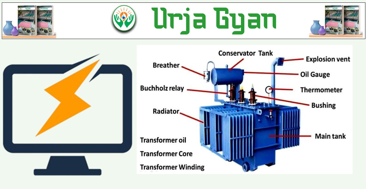
Kathmandu : This week's edition of Urja Gyan, a weekly educational series by Urja Khabar looks into the reasons behind transformer failures and its preventive measures. We talked about the functions and types of transformers in our last edition.
Common Reasons of Failure in Transformer and Solution

1. Overloading
The rating of a transformer is always expressed on its nameplate in kVA/MVA or amperes; its full-load current is similarly specified for the primary and secondary. Its operation with an overloading beyond the rating specified in nameplate will lead to break down. A 100 kVA, 11 kV distribution transformer may, for instance, have 5A full-load secondary current per phase corresponding to 400V. This cannot be measured with ordinary instruments and it is also dangerous and fatal. Overloading can be avoided by regular monitoring of LT-side current particularly in the evening once in a month.

Preventive Measure : To avoid overloading, MCCBs can be installed on LT side.
2. Unbalanced Load
An unequal load on each phase of the transformer will lead to overheating, increased technical losses, and eventual failure. Balance by measuring current on each phase using a clamp meter; shift connections from the overloaded phases to the underloaded ones.
3. Lightning Strikes
Lightning can damage transformers. To prevent this, install lightning arresters on each phase. Ensure proper grounding, as inadequate grounding increases the likelihood of damage during lightning strikes.
4. Low Oil Levels
Transformer oil serves as insulation and a coolant. Insufficient oil levels allow moisture and air to enter, reducing insulation and cooling effectiveness. Regularly check the oil level through the sight glass and top up if necessary.
5. Loose or Sparking Terminals
Improperly tightened HT or LT terminals cause sparking or heating at the point of connection and may destroy the bushings, thereby creating internal failures. Always secure cables by using crimping tools and spanners, and avoid temporary means such as hammering.
6. Silica Gel Problems
Check silica gel. If red, heat it until it turns blue and reinstall. This will ensure dry air circulates within the transformer to prevent moisture ingress.
7. Water Ingress
Loose bolts or other entry points can allow water into the transformer, compromising insulation. Maintain proper oil levels to prevent this.
8. Oil Degradation
Aging or contaminated oil reduces insulation capacity, increasing failure risk. Test oil every 5–6 years using a dielectric strength test.
9. Short Circuits
Short circuits on the LT side cause excessive currents, potentially damaging the transformer. MCCBs and properly rated drop-out fuses must be in place and functional.
10. Insulation Tests
Periodic insulation testing ensures the transformer's windings maintain adequate resistance. For 11 kV transformers, insulation resistance between HT and ground should be about 200 MΩ, while LT resistance should be about 50 MΩ.
Multiple-Choice Questions
1. What is the function of the far-right LT bushing in a distribution transformer?
(a) R Phase
(b) B Phase
(c) Y Phase
(d) Neutral
Answer: (d) Neutral
2. What material is placed in the breather of a transformer?
(a) Copper Sulfate
(b) Pebbles
(c) Silica Gel
(d) Sodium Chloride
Answer: (c) Silica Gel
3. What can be obtained by the open circuit test of a transformer?
(a) Copper Loss
(b) Iron Loss
(c) Both (a) and (b)
(d) None of the above
Answer: (b) Iron Loss
4. What must be the same for transformers connected in parallel?
(a) Voltage
(b) Phase Sequence
(c) Frequency
(d) All of the above
Answer: (d) All of the above
5. What is the internal winding connection arrangement in distribution transformers?
(a) Star/Delta
(b) Delta/Delta
(c) Zig-Zag/Delta
(d) Delta/Star
Answer: (d) Delta/Star
6. The transformer star point connected to the ground is known as
(a) Transformer Earthing
(b) System Earthing
(c) Protection Earthing
(d) All of the above
Answer: (a) Transformer Earthing
7. At the time of power transfer from primary to secondary, which of the following changes in transformer?
(a) Current
(b) Voltage
(c) Turns Ratio
(d) Frequency
Answer: (a) Current